Seite
5
Type AF3-Stahlkörper
zylindrische Zentrieraufnahme
DIN 6350
1 Satz = 3 gehärtete Drehbacken
1 Satz = 3 gehärtete Bohrbacken
Spannschlüssel und Befestigungsschrauben
Type AFR3-Stahlkörper
zylindrische Zentrieraufnahme
DIN 6350
1 Satz = 3 gehärtete Grundbacken
1 Satz = 3 gehärtete Umkehr-Aufsatzbacken
Spannschlüssel und Befestigungsschrauben
THREE JAW CHUCKS
SELF CENTERING
SYSTEM CUSHMAN
DREIBACKEN-DREHFUTTER
ZENTRISCH SPANNEND
SYSTEM CUSHMAN
Type AF3-steel body
flatback mounting
DIN 6350
1 set of 3 hardened turning jaws
1 set of 3 hardened boring jaws
key and mounting screws
Type AFR3-steel body
flatback mounting
DIN 6350
1 set of 3 hardened base jaws
1 set of 3 hardened reversible top jaws
key and mounting screws
MANDRINS DE TOUR 3 MORS
SERRAGE CONCENTRIQUE
SYSTEM CUSHMAN
Type AF3-corps acier
centrage cylindrique
DIN 6350
1 jeu de 3 mors durs intérieurs
1 jeu de 3 mors durs extérieurs
clé de serrage et vis de fixation
Type AFR3-corps acier
centrage cylindrique
DIN 6350
1 jeu de 3 semelles trempées
1 jeu de 3 mors durs rapportés
clé de serrage et vis de fixation
Bestell-Nummer
Order number
Numéro de commande
Futter
Chuck ø
Mandrin
Kegel
Taper
Cône
Technische Daten
-
Technical data
- Données techniques
Gewicht
Weight Kg
Poids
AF3
AFR3
ø A
B C D E F G H J K L M N O P V W AF3
AFR3
mm inch
400-007 400-025
315
12 ½ -
86 109 260 286 3x
M 16 5 32 50 14 155 110 120 60 140 95 30 47,0
50,0
400-008 400-026
350
14
-
93 110 300 325 6x
M 12 5 38 50 14 182,7 127 135 81,6 143 101,1 29 53,0
56,0
400-009 400-027
400
15 ¾ -
93 130 330 362 6x
M 16 5 38 50 15 182,7 127 135 81,6 143 101,1 29 67,0
70,0
400-010 400-028
500
20
-
106 130/
190 420 458 6x
M 16 6 42 52 16 192,1 127 160 78 158 114,1 33 118,0
121,0
400-011 400-029
600
23 ½ -
108 190/
260 520 560 6x
M 16 6 50 52 16 194,1 127 160 78 160 116,1 33 182,0
185,0
-
400-030
630
25
-
115 190/
330 545 586 6x
M 16 7 55 -
16 190,5 207 -
83 - 107,5 33
-
213,0
-
400-031
700
27 ½ -
117,5 190/
410 620 660 6x
M 16 8 55 -
16 192,5 207 -
83 - 109,5 35
-
223,0
-
400-032
800
31 ½ -
137,5 190 285 330 6x •
21 10 55 -
16 212,5 207 -
83 - 129,5 55
-
400,0
410 720 760
-
400-033
1000
39 ½ -
155 190 285 330 6x •
21 10 70 -
16 230 170 -
83 -
147 72,5
-
550,0
550 920 960
-
400-034
1200
47 ¼ -
155 260 300 330 6x •
21 10 70 -
16 230 170 -
83 -
147 72,5
-
980,0
600 1120 1160
-
400-035
1500
59
-
155 260 300 330 6x •
21 10 70 -
16 230 170 -
83 -
147 72,5
-
1485,0
600 1380 1440
-
400-036
1600
63
-
155 260 300 330 6x •
21 10 70 -
16 230 170 -
83 -
147 72,5
-
1620,0
600 1480 1540
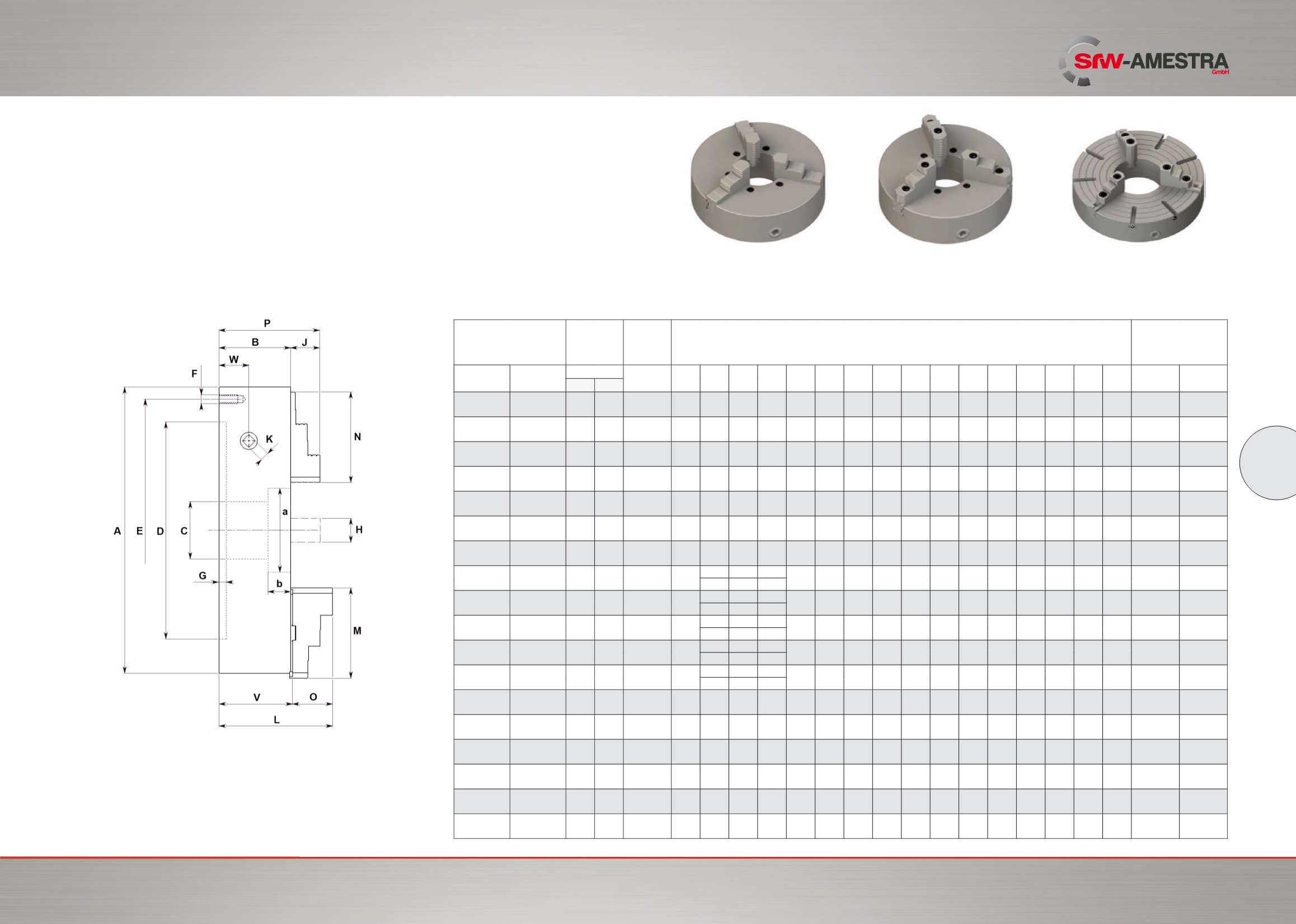
Maßtabellen für Drehfutter
Type AF/3 - AFR/3
Tables of dimension for lathe-chucks
Types AF/3 - AFR/3
Tableau des cotes principales pour mandrins de tour
Types AF/3 - AFR/3
Type AF
Ø 315 - 400 mm
Type AFR
Ø 315 - 400 mm
Type AFR
Ø 500 - 1600 mm
* Mit Langschieber Grundbacken (ISO auf Anfrage) / with long base jaws (ISO possible) / execution à semelles tiroir (ISO sur demande)
● Befestigung von vorne / mounting from the front / fixation par l´avant
Ersatzteile siehe Seiten 27-30 / Spare parts look at pages 27-30 / Pieces de rechange voir pages 27-30


